Flow Regulators – Do They Just Limit Flow or Can They Also Control It?


What exactly does a flow regulator do? You might think that it simply limits the flow rate. But that’s only half the story. Strictly speaking – and as the name suggests – a flow regulator also controls the flow, keeping it to a near-constant value. And why does that matter?
For the moment, let’s ignore today’s complicated, active regulation valves and focus on the mechanical flow regulators of old.
In a pipeline, flow is created by a difference in pressure. By this we mean that one end of the pipe is at a higher pressure than the other end. The medium always flows from high to low pressure.
In the simplest case, we can say that the higher the pressure difference, the higher the flow rate. But that’s only half the story, because while with moderate flow rates the flow is laminar, turbulence and friction in the fluid rise as the flow velocity increases, causing more energy to be dissipated, or “burned away”. With small flow rates, the relationship between pressure and flow rate is still linear, but this is not the case at higher velocities. In this range the relationship is a root function, i.e. a fourfold increase in pressure produces only about a twofold increase in flow rate.
Our flow regulators consist of a pipe section with a mechanical control insert, also called a control orifice. This orifice can be made of metal, plastic or rubber. The control orifice constricts the pipe cross-section, leaving only a defined cross-section open. This purposefully creates resistance to the flow.

As described above, a pressure difference is required to create a flow. This means that the pressure at the inlet side of the flow regulator is higher than at the outlet side. This excess pressure causes elastic deformation of the control insert, which further narrows the flow cross-section and increases the flow resistance. When the pressure falls, the control orifice returns to its original shape and the flow resistance drops. This enables the flow to be kept nearly constant, without the need for complicated electronics. You can set the target flow rate by choosing an appropriate control orifice.
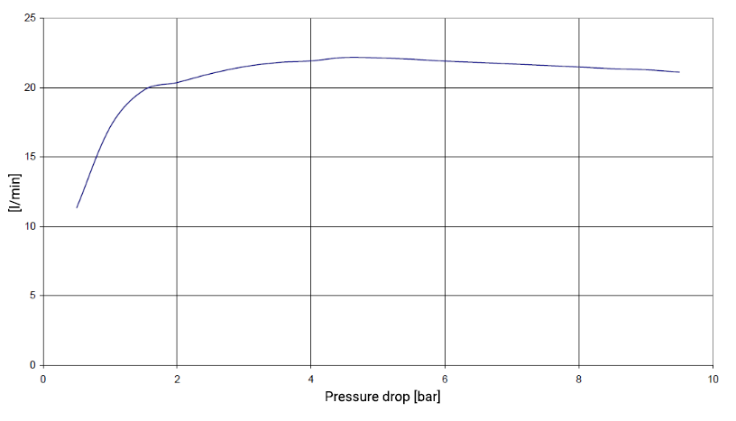
It is true that a flow regulator produces a pressure drop. A typical pressure drop curve is shown here. The horizontal axis shows the pressure drop, while the vertical axis shows the flow rate. The pressure drop shown here is equivalent to the pressure drop that drives the flow.

At low velocities, the pressure drop is small. The flow rate is below the target value. This is because the pressure difference is not yet high enough to generate sufficient flow. This fact must be taken into account when selecting a flow regulator and designing a system. In the example shown, the target flow rate is 20 l/min and the control pressure range is between 2 and 10 bar. This means that the flow regulator must be operated at a minimum of 2 bar in order to work properly.
Why regulate the flow at all? More is more, isn’t it?
There are many applications where a constant flow is advantageous, e.g. for constant heat dissipation in cooling circuits, for more even distribution in water distributors, or for finer dosing in dosing systems.
High flow rates mean high flow velocities. If the flow velocity becomes too high, turbulence increases and causes unwanted vibrations in the pipeline. A flow regulator can eliminate this effect.
You can find more information about SIKA flow regulators here.
